Evolution of Optical Transceiver Technologies and Solutions
by Will Chang

What is an Optical Transceiver?
An optical transceiver is a hardware component that transmits and receives data. It is responsible for converting the electrical signal from networking equipment into a format that can be transmitted over a physical media and then converting it back to an electrical signal at the other end.
The existence of optical transceivers greatly improves the flexibility when selecting the network equipment. Before the implementation of optical transceivers, end users had to decide on network equipment port configuration in advance. Now, they can just select the appropriate transceiver for their target application.
To ensure optical transceiver interoperability with network equipment and transceivers from other vendors, industry standards are defined for all functionalities and characteristics. There are many organizations working on transceiver interoperability, but the majority of the standards are defined by two groups. That is the Institute of Electrical and Electronics Engineers (IEEE) and Multi-Source Agreements (MSAs).
The IEEE is responsible for defining standards for the Ethernet physical layer. MSAs are groups that come together to define the transceiver form factor and electrical characteristic. Unlike IEEE, MSA is not an official standard organization, it is an agreement acknowledged by equipment vendors when developing the corresponding optical transceiver product.
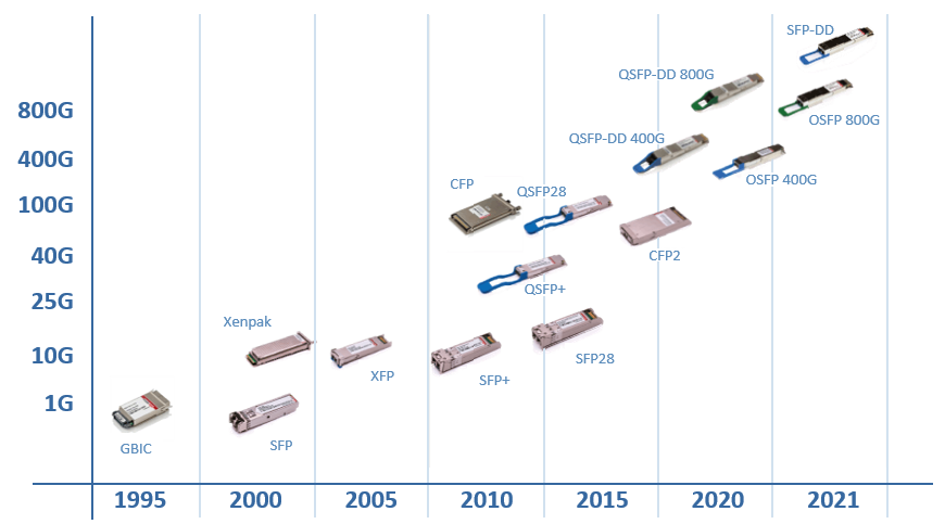
Since the optical transceiver was first defined, almost 30 years ago, there have been many types of transceiver form factors developed. GBIC, XFP and CFP form factors are less common now with SFP (Small Form-factor Pluggable) transceivers being the most popular these days.
Types of Optical Transceivers
When we are choosing a transceiver, a specific description is always used to describe the optical transceiver type, such as 10GBase-SR SFP+, 100GBase-LR4 QSFP28, 400GBase-DR8 QSFP-DD, just to name a few.
As we dive deeper into optical transceiver technology, it is important that we know what each of those descriptors represent. The information for the type of transceiver can be separated into two parts, the first part is the physical layer characteristics defined by the IEEE and the second part is the form factor and electrical interface defined by relevant MSAs.
Transceiver Physical Layer Characteristics If we take from one of our examples above, the optical transceiver specification 100GBase-LR4 QSFP28, we can breakdown the first part (100GBase-LR4) into the following information.
xxxGBase-nRm
• xxx: Is the transceiver data rate
• n: Refers to the reach, using different characters to represent different distance
• m: Number of lanes, ether the number of physical fibers or number of wavelengths carried by a fiber
Transceiver Form Factors and Electrical Interfaces Going back to our 100GBase-LR4 QSFP28 transceiver example, we can break down the second part (QSFP28) into the following information.
xSFPy-DD
• x: Represents the number of lanes at the electrical side (the side connecting to the router).
• y: Is the data rate per lane running on the electrical interface, sometimes it is ignored for convenience.
• DD: Means double density, when DD is included, there will be double the interface count available.
To summarize our example, the 100G QSFP28 transceiver at the electrical side (the side that connects to the router), it runs with a 25G rate and with 4 lanes in one direction, so it can carry a 100G data stream.
At the optical side (the side connected with fiber), there are different approaches to carry the signal. If it is a LR4 transceiver, the 4 data signals are converted to 4 different wavelengths and use WDM (Wavelength Division Multiplexing) to transmit multiple wavelengths over a single fiber. If it is a SR4 transceiver, the 4 data signals are converted to the same wavelength and transmit over 4 fibers in parallel.
The reach is decided by the wavelength and the fiber mode used (single mode or multiple mode) in general.

Meaning of transceiver specifications
400G Optical Transceiver Technology
With the growing demand on the cloud applications and new services, the network infrastructure will be migrating to higher bandwidths.
According to Dell’Oro Prediction 2022 , the deployment of 400G routers is accelerating in both data center and service provider verticals. We can expect the migration to a 400G network starts from the IP Core and DC Core as the pictures shown below.
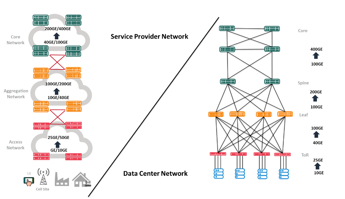
Migration of the network configuration
As we mentioned in previously, the factors defining the port’s speed are the data rates of single lane and number of lanes. In order to hit 400G, the optical transceiver utilizes PAM4 to double the data rate to 50G and using QSFP-DD to provide 8 lanes to carry the data.
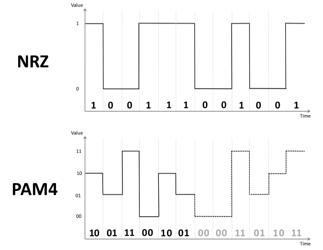
PAM4 doubles the data rate compare to NRZ
Various physical interface implementations can enable different types of 400G transceivers that can be used in different scenarios. Here are some of the different ways optical transceivers can meet 400G ethernet speeds:
• SR8 optics: Uses shorter wavelength and 8 parallel multiple mode fibers carrying 50G data each for short distance applications of about 100m.
• DR4 optics: Uses longer wavelength and 4 parallel single mode fibers carrying 100G data each for applications around 500m reach.
• LR4/LR8 optics: Uses WDM (Wavelength Division Multiplexing) to multiplex 4x100G or 8x50G wavelengths into a single mode fiber for the applications up to 10km.

400G optics reach and its applications
Development of 800G and 1.6T Transceivers
Looking forward to 800G and 1.6T pluggable transceivers, multiple organizations have been working on this topic from different angles.
IEEE:
In 2022, the IEEE started the Beyond 400G Study Group , which works on the definition of 800G/1.6T standards and evaluating the feasibility of 100G per lane and 200G per lane optical technology.
ETC (Ethernet Technology Consortium):
Before IEEE starting the study of an 800G standard, the ETC (formerly 25 Gigabit Ethernet Consortium) had released specifications for an 800G Ethernet by leveraging existing 400G specifications to build 8 lanes with 100G per lane standard.
800G Pluggable MSA:
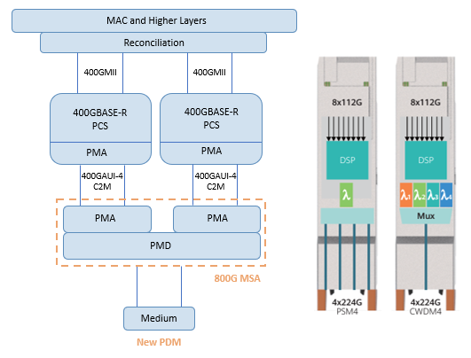
800G Pluggable MSA covers the optical PMD specification as well as the multiplexing of 100GbE and 400GbE signals on the host side. PMD (Physical Medium Dependent layer) is part of the PHY and defines how to transmit and receive data over physical medium. 800G Pluggable MSA proposed a few solutions to enable 8x100G, 4x200G and 8x200G interfaces.
QSFP-DD MSA:
A QSFP-DD800 MSA has merged back into QSFP-DD MSA, their approach is adopting 100G per lane to enable 800G on QSFP-DD form factor pluggable and potentially achieve 1.6T if 200G per lane can be realized.
OSFP MSA:
OSFP (Octal Small Form Factor Pluggable), as the name implied, defines 8 high speed electrical lanes to enable 400G and 800G optical transceivers with 50G and 100G per lane. And a 16 lanes solution OSFP-XD was also announced to support 1.6T with 100G per lane technology.
Co-Packaged Optics:
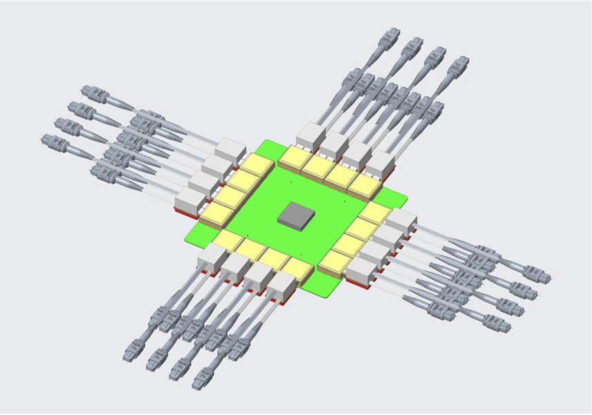
To overcome the electrical limitation and support a higher signal rate, the idea of a CPO (Co-Package Optics) was proposed few years back in 2019.
The idea is to put electro-optical conversion components as close as possible to the ASIC and minimize the loss and distortion of the electrical signal during transmission.
There are many advantages such as higher bandwidth, power efficiency and higher front panel density. However, the increased ASIC complexity and difficulty of repair would be a great challenge to implement this solution.
Emerging Fiber Optic Transceiver Technologies
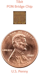
With the advancement of silicon technology, the computer chip is getting smaller yet, it has more computing power than ever before. Different parties are integrating features which were available on big box only into a small DSP (Digital Signal Processor) no bigger than 1 cent coin.
An optical transceiver now is no longer a transmitter and receiver only, extra features enabled can help to simplify a network’s architecture and enable more flexible network configurations. Some examples of how more features can be introduced into optical transceivers are TiBit MicroPlugsTM, Open XR Optics and OpenZR+ Optics.
TiBit MicroPlugTM
Tibit MicroPlugTM OLT is developed by TiBit Communications. They integrated all the features from a big OLT chassis into a SFP+ transceiver module. With the help of this pluggable OLT transceiver, service providers can combine two layers of configuration (OLT chassis and aggregation router) into a single layer. A router could offer services to terminate PON traffic and work as a general aggregation router at the same time.
Open XR Optics
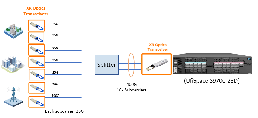
Open XR is a new standard introduced by Infinera and it is now a MSA (Open XR Optics Forum). It is the industry’s first point to multipoint coherent pluggable transceiver, which provides great flexibility in network configuration.
With the introduction of Digital Subcarrier Multiplexing (DSCM) technology, an optical signal can be further divided into multiple lower speed signal and distributed to different fibers.
The intermediate aggregation router could potentially be removed and the capacity of each link could be allocated dynamically in the central hub.
OpenZR+ Optics
OpenZR+ was designed to combine the efforts from two industry standards to offer flexible and interoperable coherent solution and cover more application scenarios. The coherent technology increases the transmission speed and distance by adopting higher order modulation, stronger FEC (Forward Error Correction) and transmitting signal with DWDM on two polarizations.
The feasible applications proposed by the OpenZR+ MSA for OpenZR+ transceivers include access/metro aggregation, regional DCI and long haul. It can eliminate the use of transponder and simplify the network architecture.
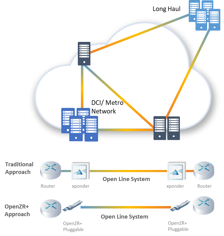
Application scenario of OpenZR+
Support for Pluggable Transceivers
UfiSpace is enabling the latest pluggable transceiver technologies to be deployed by providing the support needed in our leading edge network equipment.
Recently, UfiSpace is working with TiBit MicroPlugTM, Open XR Optics and OpenZR+ Optics closely to support service providers adopt next generation solutions using optical transceivers. For more information, please contact our sales team.
For more information about UfiSpace's solutions supporting pluggable transceivers, please contact our sales team.

